Chapter 7 Fire Protection and Flame Retardation of Cables
Article 7.0.1 For cable loops that are vulnerable to external influences on fire, or cable loops that may cause fire accidents and cause serious accidents, must be constructed in accordance with the design requirements for fire retardant measures.
Article 7.0.2 fire and flame retardant cable should take the following measures:
1. In the hole where the cable passes through the shaft, wall, floor or into the electrical panel or cabinet, it is sealed tightly with fireproof plugging material.
Second, in important cable trenches and tunnels, fire fighting walls are set up as required or with soft refractories.
Third, the cable of the important circuit can be laid separately in a special channel or in a fireproof closed tank box, or fireproof paint and fireproof tape can be applied to it.
4. Apply fire-retardant paint or fireproof tape on both sides of the power cable connector and adjacent cables 2 to 3m long.
Fifth, the use of fire-resistant or flame-retardant cable.
Six, set the alarm and fire extinguishing device.
Article 7.0.3 Fire-retardant and flame-retardant materials must be technically or product-approved. During use, construction measures should be submitted according to design requirements and materials use techniques.
Article 7.0.4 shall be diluted with a certain concentration of paint, stirring evenly, and should be brushed along the length of the cable brushing, brushing thickness or number of times, interval should be consistent with the material requirements.
Article 7.0.5 should be pulled tightly when wrapped around the package. The number or thickness of the wound should be in accordance with the material requirements. After the wrapping is completed, it should be firmly tied at regular intervals.
Article 7.0.6 When plugging cable holes, the plugging shall be tight and reliable. There shall be no obvious cracks and visible voids. The larger holes shall be filled with a refractory lining before sealing.
Article 7.0.7 Fire doors on fire-resisting walls shall be tight and holes shall be sealed. Fire-retardant tapes or coatings shall be applied to the cables on both sides of fire-retardant walls.
Chapter VIII Acceptance and Acceptance of Works
Article 8.0.1 shall be inspected in accordance with the following requirements at the time of acceptance:
First, cable specifications should be in accordance with the regulations; neatly arranged, no mechanical damage; signs should be installed complete, correct and clear.
Second, the cable's fixed, bending radius, the relevant distance and the wiring of the metal sheath of the single-core power cable, and the phase sequence arrangement shall meet the requirements.
Third, the cable terminal, cable connector and oil-filled cable oil supply system should be installed firmly, there should be no leakage phenomenon; oil-filled cable oil pressure and meter setting values should meet the requirements.
Fourth, grounding should be good; oil-filled cable and sheath protector grounding resistance should be designed.
5. The phase of the cable terminal should be correct, and the metal components such as the cable support should be intact.
Sixth, the cable trench should be free of debris, complete cover, the tunnel should be no debris, lighting, ventilation, drainage and other facilities should meet the design.
7. Directly buried cable path signs should conform to the actual path. The route signs shall be clear, firm, with appropriate spacing and shall comply with the requirements of Article 5.4.6.
8. On both sides of the underwater cable line, the signs and night lighting devices in the banned anchor zone shall meet the design.
Nine, fire prevention measures should meet the design, and the construction quality is qualified.
Article 8.0.2 The covert works shall be checked and accepted in the construction process and a visa shall be made.
Article 8.0.3 When submitting inspections, the following documents and technical documents shall be submitted:
First, the cable route path agreement file.
Second, design data drawings, cable inventory, change the design of the supporting documents and as-built drawings.
Third, buried cable transmission line laying position map, the ratio should be 1:500. Underground pipelines in dense sections should not be less than 1:100. In areas where the pipelines are sparse and the terrain is simple, the ratio can be 1:1000; for parallel laying of cable lines, one drawing should be used together. The map must indicate the relative position of the lines and a cross-section showing the underground pipeline.
Fourth, the manufacturer provides product specifications, test records, certificates of compliance and installation drawings and other technical documents.
Fifth, the hidden engineering technical records.
Six, the original record of cable lines:
1. The type and specification of the cable, the actual total length and segment length of the cable, the type and installation date of the cable terminal and connector;
2. Names and models of insulation materials filled in cable terminals and connectors.
Seven test records.
Appendix I Explanation of Norms
Schedule 1.1 This specification norm interpretation This specification is explained by nouns
Metal Sheaths collectively known as lead sheaths and aluminum sheaths
Armored metal strips with radial reinforcement and metal wires with longitudinal reinforcement are collectively referred to as armoring.
Metal sheath Metal shield and armored collectively. Sometimes metal sheaths or armor are also referred to as metal sheaths.
Cable termination A device installed at the end of a cable so that the cable is connected to other electrical equipment or overhead transmission lines and maintains the insulation until the point of connection is called a cable termination.
Cable joints Devices that connect the cable with the conductors, insulation, shielding, and protective layers of the cable to make the cable line continuous are called cable joints.
Cable Brackets When cables are laid in place, the devices used to support the cables are collectively referred to as cable brackets, including common brackets and bridges
Cable bridges are composed of straight sections, non-linear sections, accessories, and hangers of trays (brackets) or ladders to support cables with a continuous rigid structural system.
Henan Sanheng Industrial Co., Ltd. , founded in 2000, It is one of the top wire and cable manufacturers in China's wire and cable industry for nearly 20 years. the company has more than 5 production lines.
The production cable can be divided into more than 50 varieties and subdivided into 1000 specifications.All products have passed national certification, such as China compulsory certification, bv certification, Nigerian SONCAP certificate, China national industrial certification, etc. China national industrial production license, etc.It also has the ability to produce products that meet international standards, such as iec, ce, rohs, etc.
If you want to buy wires and cables, you can ask the customer service staff and we will get back to you as soon as possible.
-

PVC Insulated Aluminum Cable
Conductor:Aluminum Conductor of Class 1/2 (Solid)
Insulation:PVC Compound
Insulation Color:Red, Blue, Green, Yellow, Brown, Black, Grey, White, Pink, Orange, Yellow/Green
-

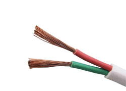
Flexible Flat Cable
Conductor:Stranded Copper Conductor of Class 5/6 (Flexible)
Insulation:PVC Compound
Insulation Color:Red, Blue, Yellow/Green or as request
-

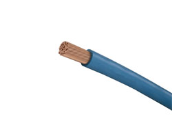
Single Core Flexible Cable
Conductor:Stranded Copper Conductor of Class 5 (Flexible)
Insulation:PVC Compound
Conductor Color:Red, Blue, Green, Yellow, Brown, Black, Grey, White, Pink, Orange, Yellow/Green
-

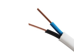
Twin and Earth Cable
Conductor:Class 1/2 copper conductor (solid)
Insulation:PVC Compound
Insulation Color:Red, Blue, Yellow/Green or as request


